Reduced Heat Transfer
A deposit layer can restrict heat transfer from the heating surface into the fluid.
 +86 13080774668
 contact@xgthermal.com
 Mon-Fri 9:00-18:00 UTC+8


Certified Manufacturer
ISO 9001:2015
China's Leading
Heating ManufacturerManage fouling and coking risk through thermal design, surface loading, flow management and heating architecture selection.
The fluid, heating surface and operating conditions must be considered together—not just the required outlet temperature.
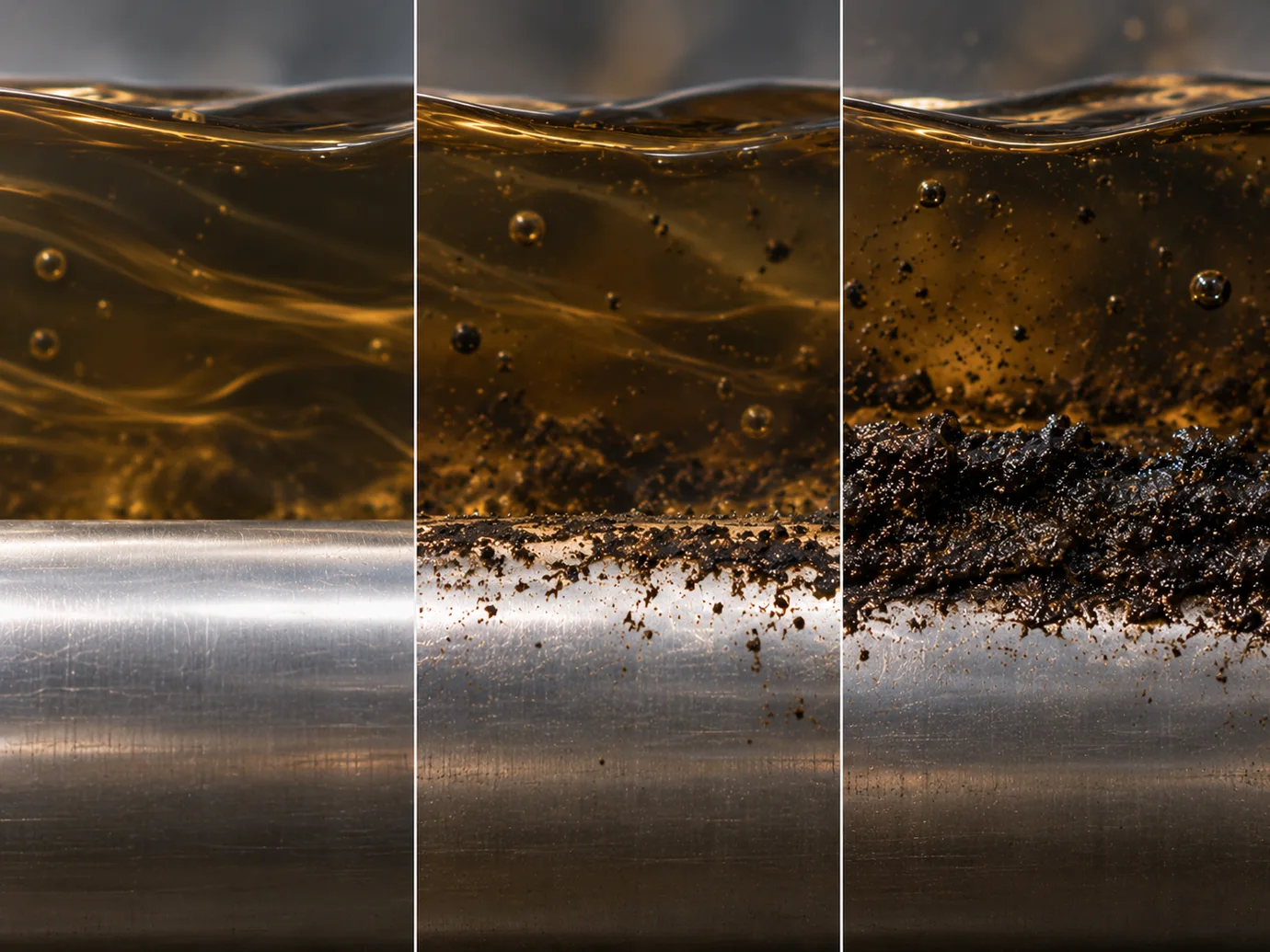
Deposits add thermal resistance between the heating surface and process fluid. Heat transfer can deteriorate, affecting the heating duty and operating conditions.
A deposit layer can restrict heat transfer from the heating surface into the fluid.
Maintaining the same duty may require a higher surface temperature as thermal resistance increases.
Deposits can contribute to higher energy use, more frequent cleaning or heater damage.
Managing surface conditions and deposit buildup supports more stable operation.
Further thermal degradation or deposition may occur depending on the fluid and operating conditions; this progression is not inevitable.
Coking tendency depends on the fluid and its local conditions near the heating surface, as well as the broader operating envelope.
The bulk fluid temperature alone does not define coking risk.
For the same heating duty, a larger effective heated surface reduces average surface heat flux. This can help control local surface temperature under comparable fluid and flow conditions.
Same heating duty · smaller heated area
Same heating duty · larger heated area
Lower watt density is not always the best overall design. Selection must also consider the fluid, flow conditions, heating duty, heater size, process constraints and practical or economic requirements.
Conceptual comparison only. Arrows illustrate heat distribution, not measured temperatures or numerical design recommendations.
Flow across the heating surface carries heat into the process fluid. Poorly swept regions may allow local surface temperatures to rise, increasing fouling or coking risk.
Heat must be removed from the heating surface as effectively as it is generated.
Generic conceptual passages—not a proprietary heater geometry, flow simulation or measured thermal result.
The appropriate heat-transfer arrangement depends on process conditions, fouling tendency and project objectives. No architecture removes the need to assess the fluid and the heated surface.
Electric heating surface → process fluid
A direct heat-transfer path can provide a compact arrangement. The heating surface is exposed to the fluid, so surface loading, surrounding flow and fluid thermal stability matter.
Crude Oil Circulation Heater Immersion HeaterElectric element → intermediate medium / boundary → process fluid
The electric element is separated from direct process-fluid contact. The process-side heat-transfer surface can still foul; fluid, surface temperature and flow conditions remain important.
Vacuum-Assisted Phase-Change Indirect HeaterElectromagnetic energy → metallic process boundary → process fluid
Heat is generated in a metallic boundary and transferred to the fluid. Surface conditions, heat flux and flow still require evaluation for the application.
Explosion-Proof Induction HeaterProcess control and heater protection serve different purposes. Outlet temperature indicates whether the process objective is being met; surface or sheath monitoring can provide additional information for high-limit protection.
Outlet / bulk temperature
Surface / sheath temperature
Share the available process information and operating evidence. Observations from an existing heater can help identify the heating problem and guide the engineering review.
Existing operating evidence helps distinguish a surface-temperature issue from fluid, flow or deposit-related factors.
Practical answers about fouling, coking and heating-surface conditions in electric process heating.
Coking can occur when a fluid thermally degrades near a heated surface. Fluid composition and thermal stability, local surface or film temperature, heat flux and flow conditions all influence the tendency. Not every deposit is coke; solids, scale and other contaminants can also cause fouling.
No. Lower surface loading can reduce local heat flux, but heater design must also consider fluid properties, flow conditions, required heating duty, equipment size and process constraints.
Heat transfer requires a temperature difference. During heating, the surface is normally hotter than the bulk fluid. The difference depends on heat flux and heat-transfer conditions; a deposit layer adds thermal resistance and may increase the surface temperature needed for the same duty.
Flow helps carry heat away from the heating surface. Low-flow or poorly swept regions can contribute to local hot spots. The appropriate flow conditions depend on fluid properties, passage geometry and pressure-drop constraints; there is no universal velocity for every application.
No. Indirect heating changes the heat-transfer interface and separates electric heating elements from direct process-fluid contact. The process-side heat-transfer surface can still foul, and risk depends on fluid properties, surface temperature, flow conditions and overall thermal design.
Provide the fluid composition and properties, operating flow and temperatures, heating duty and existing heater details. Deposit photographs, cleaning records, failure history and any sample analysis can help the engineering review.
Share your process conditions and operating evidence. XGTHERMAL can help evaluate the heating challenge and a suitable electric heating approach.
