Thermal equipment
Electric thermal oil heater, gas heat exchanger and elevated expansion vessel.

ISO-Certified Manufacturer
ISO 9001 · 14001 · 45001Electric Heating Expertise
Manufacturing Since 1992A 1,200 kW indirect electric heating skid for molecular sieve regeneration at a natural gas processing facility in Xinjiang, China.
The project configuration below summarizes the supplied equipment and its process application.
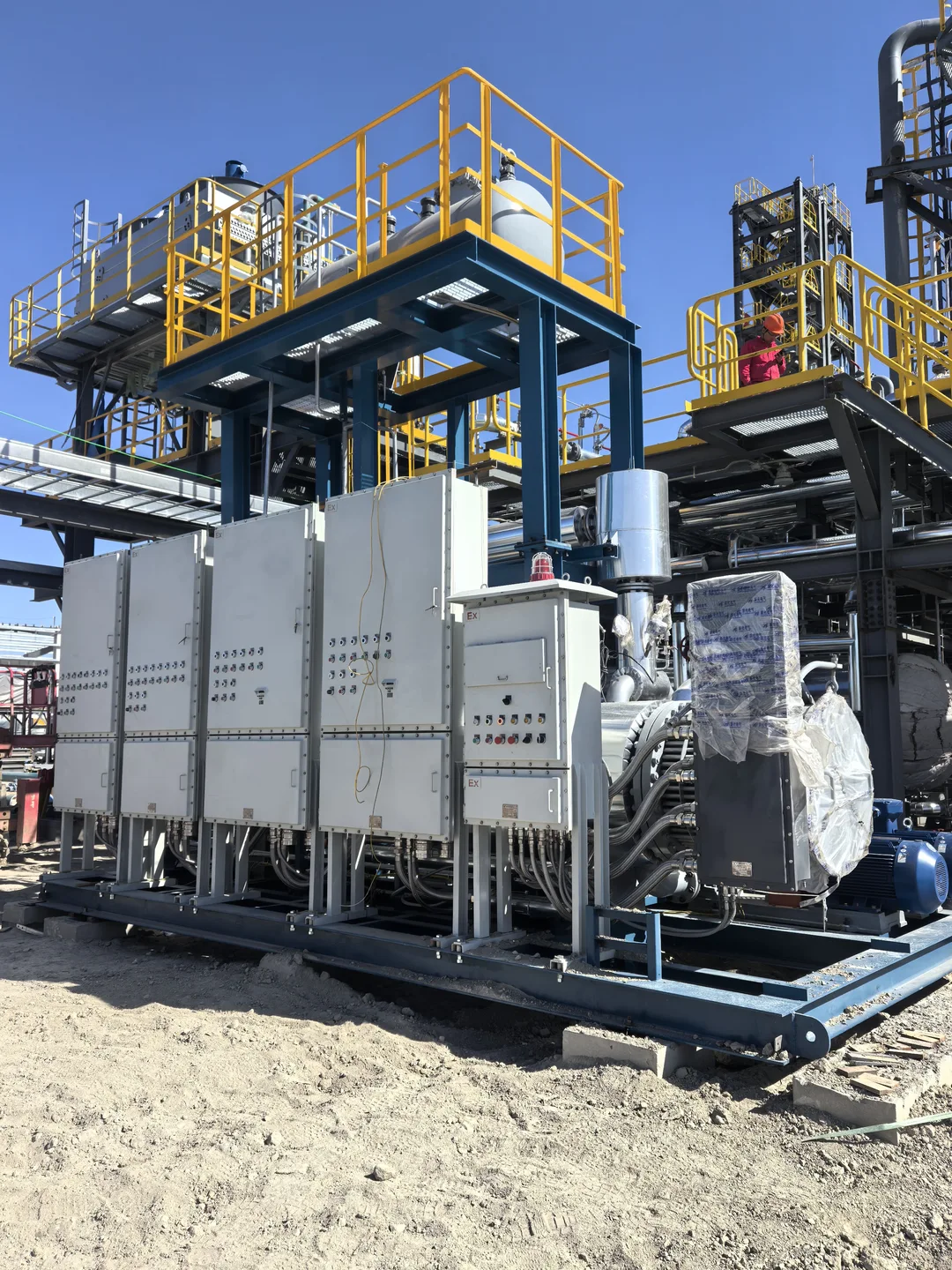
The dehydration unit required hot regeneration gas to remove moisture from the molecular sieve beds. The package had to deliver the required heat to pressurized natural gas and accommodate cold outdoor conditions.
At this scale, the heating duty also shaped the electrical distribution, thermal oil circulation and protection strategy. The package brought these systems together on a common skid for connection to the plant.
Equipment capacities, interfaces and controls are matched to the project application.
The integration and handover scope documented for this project.
Electric thermal oil heater, gas heat exchanger and elevated expansion vessel.
Duty and standby circulation pumps, insulated piping and skid-mounted valves.
Heater power cabinets, PLC controls and interlocks integrated with the package.
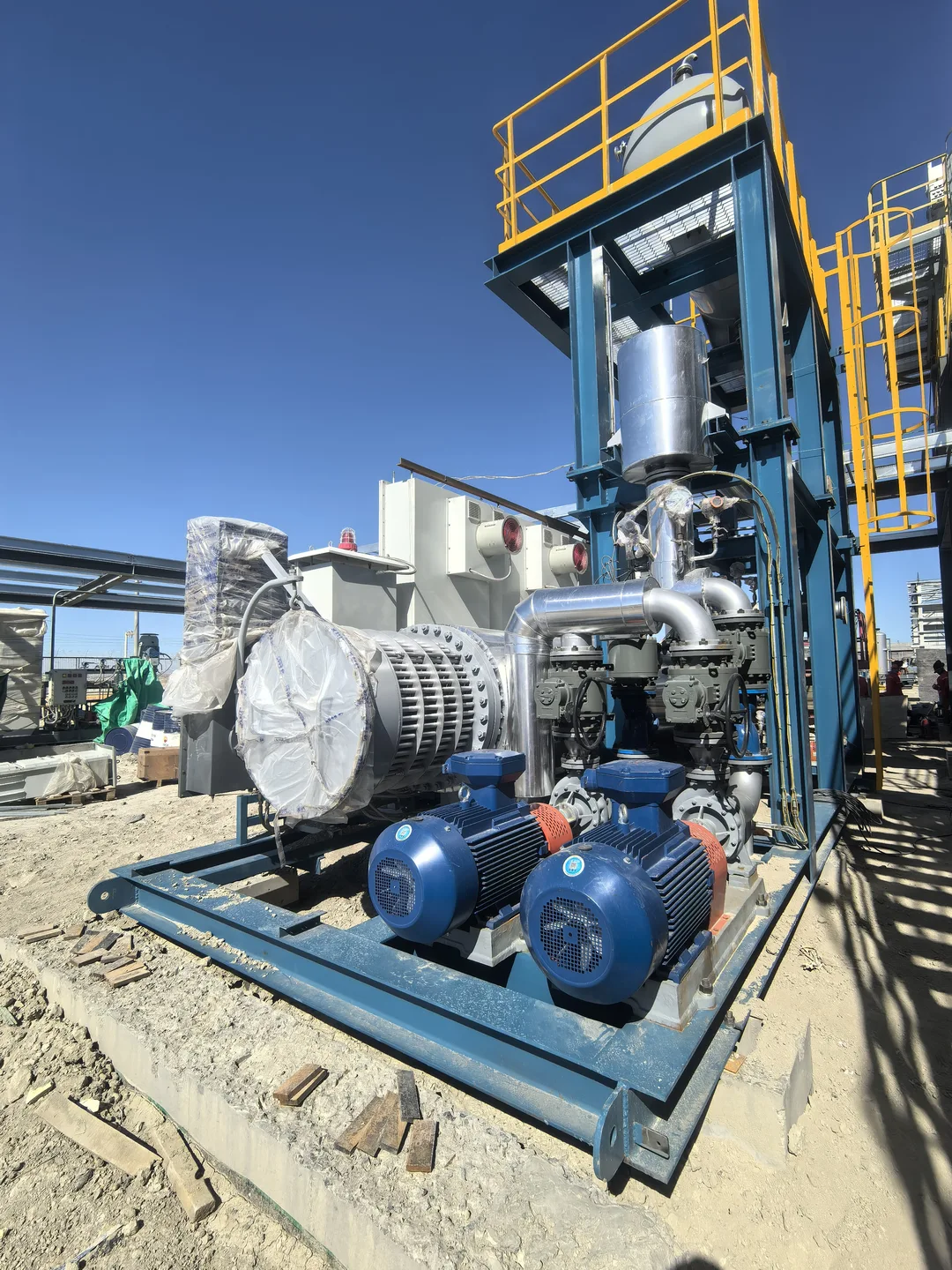
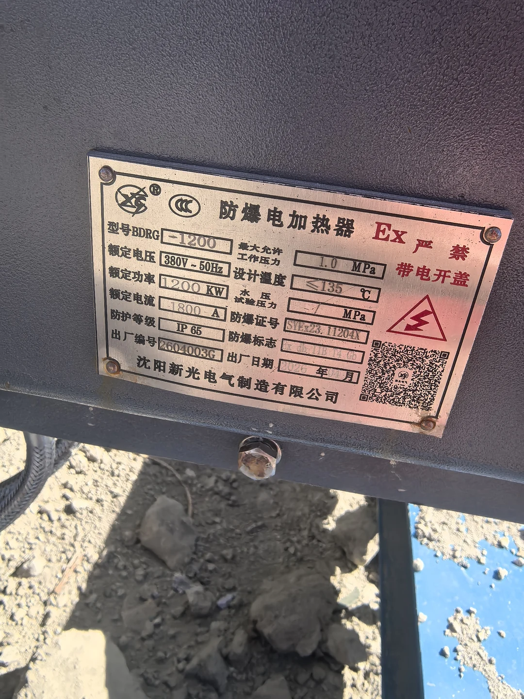
The heater nameplate and gas-side exchanger describe separate components. Efficiency and temperature control figures are project specifications.
| Parameter | Specification |
|---|---|
| Heater model | BDRG-1200 |
| Equipment tag | PE-10402 |
| Rated power | 1,200 kW |
| Rated voltage and frequency | 380 VAC / 50 Hz |
| Rated current | 1,800 A |
| Explosion protection | Ex db IIB T4 Gb (certificate SYEx23.11204X) |
| Ingress protection | IP65 |
| Process medium | Molecular sieve regeneration gas (natural gas) |
| Reported gas processing capacity | 180,000 m³/day |
| Gas inlet temperature | 50 °C |
| Gas outlet temperature | 230–240 °C |
| Process gas operating pressure | 2.8–4.0 MPa(g) |
| Gas-side exchanger design pressure | 5.0 MPa |
| Heater nameplate limits | Maximum allowable working pressure 1.0 MPa; design temperature ≤135 °C |
| Process connections | DN100, weld-neck (WN) raised-face (RF) flanges |
| Heating method | Electric resistance heating with an indirect thermal oil circulation loop |
| Efficiency figures in the project specification | Thermal efficiency ≥95%; heating efficiency ≥98% |
| Load adjustment in the project specification | 20–120%, with stepless SCR control |
| Specified temperature control accuracy | ±2 °C, with primary and auxiliary heating stages |
| Circulation pumps | Two air-cooled horizontal centrifugal thermal oil pumps, one duty and one standby |
| Expansion vessel | Nitrogen blanketing and a magnetostrictive level transmitter |
| Control system | PLC, 10-inch touchscreen and Modbus RTU/TCP communication with station controls |
| Project ambient temperature range | −35.9 to 42.9 °C |
| Heater serial number and manufacture date | 2604003G / April 2026 |
| Manufacturing standards listed in the project specification | GB/T 150, GB/T 151, NB/T 10936, JB/T 2379, SY/T 0524 |
The electric elements heat the circulating thermal oil. A separate exchanger transfers heat to the regeneration gas, keeping the process gas out of the electric heater vessel.
Gas outlet temperature feedback adjusts heater output. Overtemperature, low oil level and loss of circulation are monitored through the package protection system.
The skid incorporates cabinet heating, instrument insulation and heat tracing where needed for cold-weather service.
The electrical, thermal oil and process gas systems were assembled as a package before shipment, reducing the amount of interconnecting work left for site installation.
The 1,200 kW package uses an electrically heated thermal oil loop to serve the regeneration gas duty without a fired heater in the package.
Share your specifications or drawings with our engineering team.